|
|


 |
| Manufacturer | UNAOHM |
| Model | G45 |
| Year | 1960 |
| Tubes | EY86 ECC82 ECC81 ECF80 ECC81 5UP1 EZ88 ECC88 ECC88 ECC88 ECC82 |
| Power supply | 110-220 Vac |
| Size | 18x40x30 |
|
The instrument described above is an old UNAOHM scope built about at the beginnin of the '60. Its typical bandwith is from 0 (dc) to 1Mhz about, so an oscilloscope useful only for BF and MF measuring/adjustements. The employeed CRT tube is a 5UP1 with green phospores. After its restoration now works perfectly again. In order to display the 5UP1 data sheets click HERE |
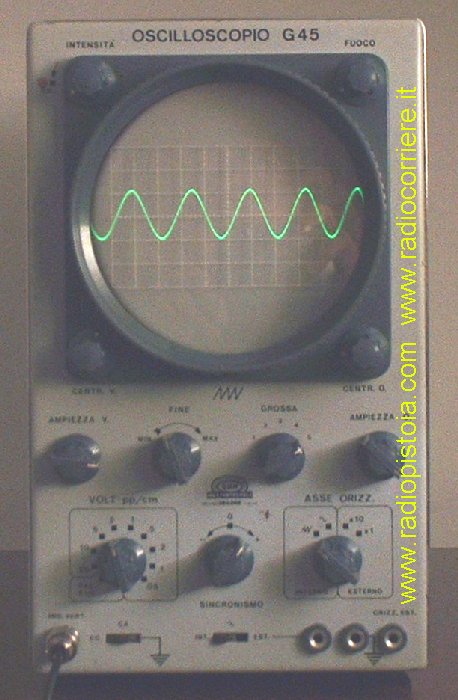 |
Detailed view of the instrument while scoping. The input signal is a 100Khz - 4Vpp sine wave and you can see the good geometry of the instrument. The squares scale has been adjusted too to obtain an accetable resolution. |
|
 |
|
 |
 |
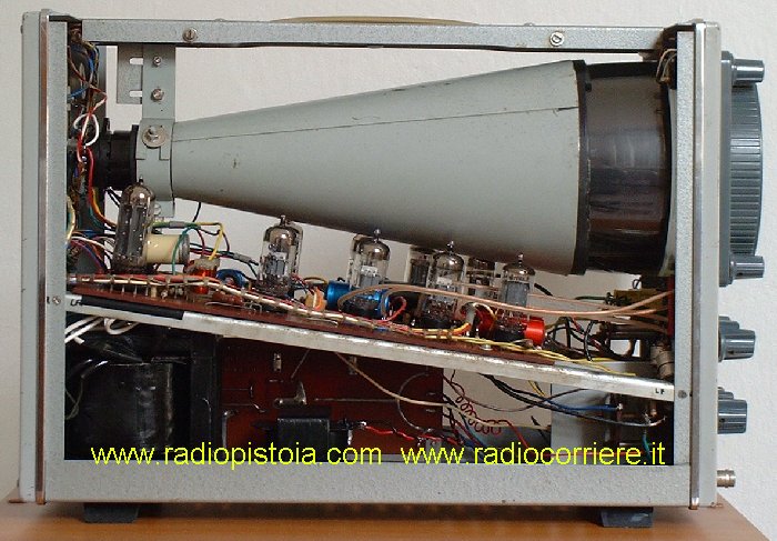
Another view of the instrument taken from the left side, this time with the magnetic shield all around the CRT removed. You can see the BIG power supply trasformer. This was the only component I had repaired. The rest of the scope has worked fine at the first time after applyng power. |
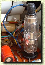
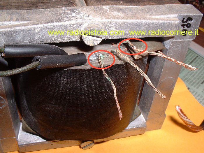
On the left is the detailed view of the damaged power supply trasformer before its restoration. All the output wires and many coils unfortunatly was in short circuit.The component was completly dissassembled (!), repaired with new wires and closed again. |
 |
 |
After a black hand painted and ... looks new again :) |
|
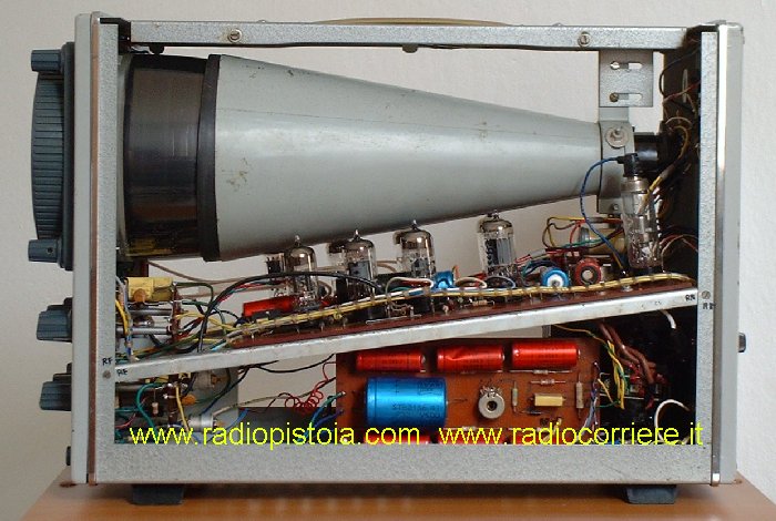
View of the instrument during its restoration. As you can see
has been complelty disassembled. The time required to make this
work, with the trasformer repairing was about one week Important tip: While disassemblig/reassembling instruments like this or more generally receivers it's VERY important to write down very accuratly each cable, socket, switch BEFORE its removal. This because after days in the reverse operation it is very easy to forget the right routing... Believe me ! |
 |
 |
Panoramic view of the components after ... washing :) These components, tubes, CRT and platics was whashed with... water and soap. Naturally was left two days without reassembling in order to obtain a PERFET drying. |
Another picture taken during the restoration work. It was an hard operation due to the big quantity of wires all around the instrument. Note the long.. very long colored cable with the potentiometers and switches just removed.. |
 |
|
|