|
|


 |
| Builder | Radiomarelli |
| Model | 10A05 |
| Year | 1940 |
| Bands | LW-MW-TW (note) -SW1-SW2-SW3-SW4 |
| Tubes | 6SA7-6NK7-6Q7-6V6-5Y3-6E5 |
| Tuning | Supereterodyne with MF of 455Khz |
| Power | 80-220 Vca |
| Size | 59X30X40 |
| Audio drive | A 6V6 power thetrode |
| Magic eye | Yes, a 6E5 |
| Note | This receiver could works with a low power voltage (80V) in this case the power transformer will increase the voltage to the rights values. The "TW" band means "Tropical Waves" with a range from 40 to 110 meters. |
 |
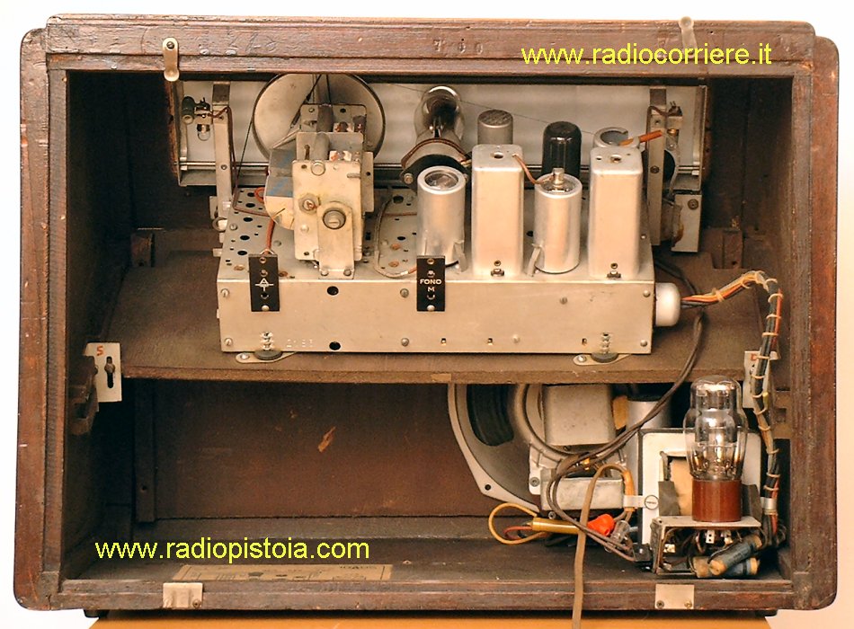
This is the internal view of the receiver. Note that this chassis is mounted inside the wood cabinet with a 45 degree angle from its horizontal position. You can see this better in the top picture. In the center of this picture the magic eye 6E5, in the right the tuning capacitor. |
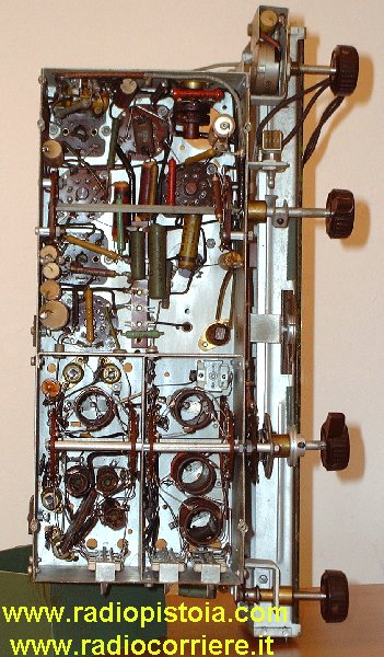
In this picture you can see the bottom view of the receiver. Note the great attention in the AF coils shields system. The band switch was repaired by me because some contacs in the local oscillator section were damaged, and the receiver dead in the OC's bands. |
 |
|
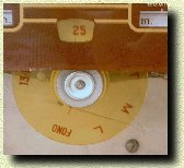
This is a detailed view of the bands indicator plate. There is a small wire from this indicator to the band swicth in order to rotate this disk when attemtping to change the bands. |
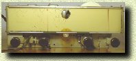
| In this receiver there are two tuning indicators (the red ones) and they are moved togheter with the tuning knob. |
 |
|
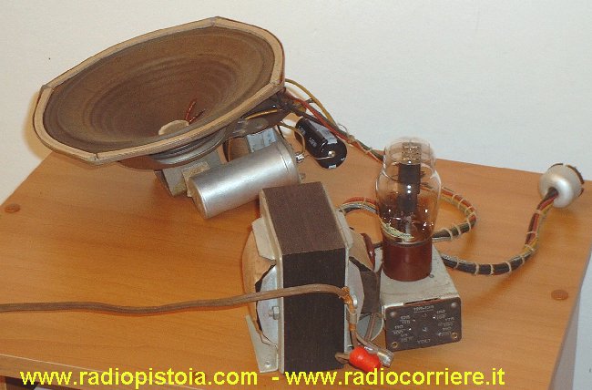
This is the power supply and loudspeaker section. As inside many top class receivers the power supply section is separated from the radio chassis, this to reduce hum and noise.. I added the black capacitor you can see just behind the lodspeaker because the original one was damaged. In this case too the damaged component was not removed from its original position. |
| A nice detailed view of the tuning scale of this receiver. Pratically new, without any scracth. In order to light it there are two lamps powered with the tubes heather voltage. |
 |
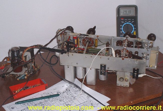 |
General view of the first "warming up" of this receiver, in my laboratory. Once repaired the band switch this receiver was pratically finished. In the rear of the picture you can see my digital multimeter that now is displaying the anodic supply (291V about). |
|
|