|
|


 |
| Builder | Marconiphone |
| Model | 296 |
| Year | 1932 |
| Bands | OM - OL |
| Tubes | MX1 VMS4B MHD4 PX4 U12 (Marconi originals) |
| Tuning | Supereterodyne |
| Power | 110-220 Vca |
| Size | 46x41x28 |
| Audio drive | PX4 triode in A class |
| Magic eye | Yes, but a "fluid indicator" |
| Note | This Marconiphone is the best radio of my collection. It is english original, made about in the 1930-1932, and after my restoration works fine.. |
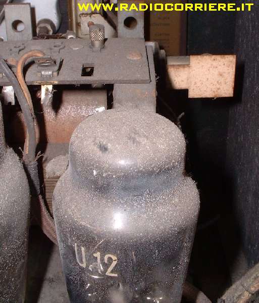 |
Pictures taken before my restoration, you can see tons of dust above the tubes and the chassis. This tube is the U12 rectifier, a double diode with direct heathing. The heathers of this receiver are supplied with a 4.5V alternate voltage. |
The wood cabinet, before the restoration. Two days of job in order to restore it to the original state. |
 |
 |
Picture taken during the firts "warm up & test" of the receiver. In this old radios is important to supply the main power with a variac, in order to increase the voltage applied in little steps. Otherwise capacitors blast or tubes heather broken could result. |
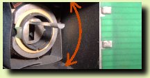
This is a detailed view of the tuning indicator. It's a coil inserted between the anodic supply and the MF tubes with a shutter and a little lamp. When the receiver is tuned on a station the anodic current of the MF tube increases and this move the shutter down. The lamp behind the shutter create a shadow on the green scale, this to display the exact tuning of the receiver. |
 |
 |
Detailed view of the big loudspeaker. In this old radios the magnetic field in order to operate the speaker is generated by a coil (the red one) This coil is powered by the anodic supply. |
Rear view of the chassis. You can see the BIG triode PX4 (the audio power tube) and on the right corner a variable resistor. This resistor balances the heather voltage against the ground, this to reduce the hum. Infact in this receiver the tubes are without catode, they works with a direct heathing. |
 |
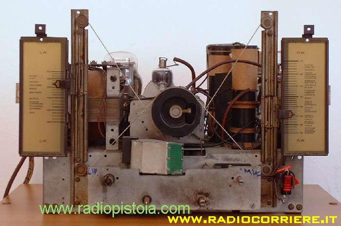 |
Front view of the receiver. You can see the tuning scales (OM and OL) and the central pulley connected to the variable capacitor. In this receiver the power on swicth is the band selector. There is a position where the receiver powers off. |
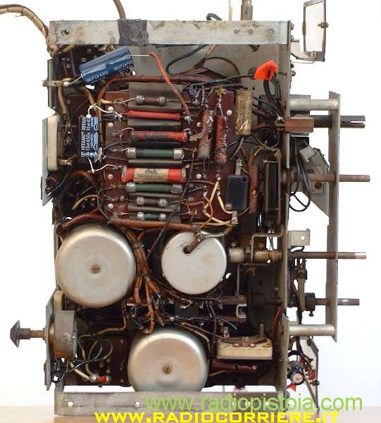
Behind view of the chassis. All the resistors and capacitors are mounted near on a "capacitor box". On the left you can see the two new electrolitic capacitors. The big circles with a screw in the middle are the MF transformers, many different from the newest one. |
 |
|
|