|
|

|
| Builder | Nordmende |
| Model | Fidelio 58 |
| Year | April, 26 1957 |
| Bands | LW - SW - MW - FM - Phono |
| Tubes | ECC85 - ECH81 - EF85 - EM84 - EABC80 - EL84 |
| Tuning | Supereterodyne with M.F. 469Khz and 10.7Mhz |
| Power | 110-220 Vac |
| Size | 64x40x25 |
| Power audio tube | Penthode EL84 |
| Magic eye | EM84 |
|
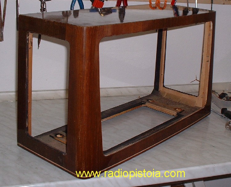
Close
view of the wood cabinet before its restoration. It was not
necessary a great work, the cabinet was in a quite good conditions,
this due to the age of this radio too. (1957)
|
|
 |
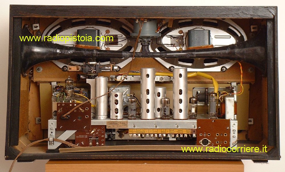
Here you can see the internal of the radio the day just arrived in my... garage. On the bottom of the chassis , over a ground metallic shield I found its original schematic diagram.. A nice surprise! |
|
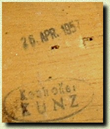
A detailed view of the manufacturing date stamp, inside the wood cabinet. For curious people the april, 26 1957 was a friday :) |
|
|
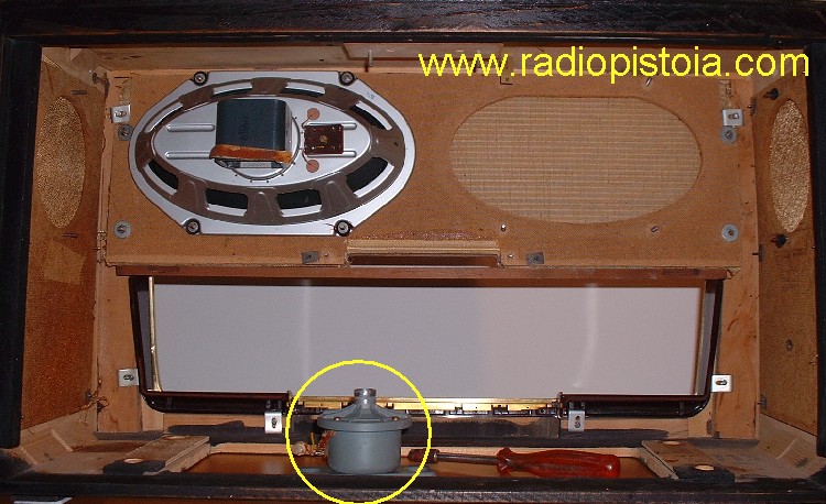
Here you can see the receiver while reassembling, after the cabinet restoration. Note one of the two big speakers and marked with a yellow circle the 3D tweeter. Infact in this receiver there is a bakelite horn (see the top picture) wich expand the produced sound and seems like a 3D effect. In the Grungid 3D KLANG there is a similar circuit too. |
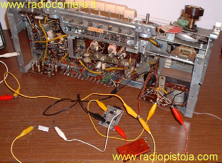
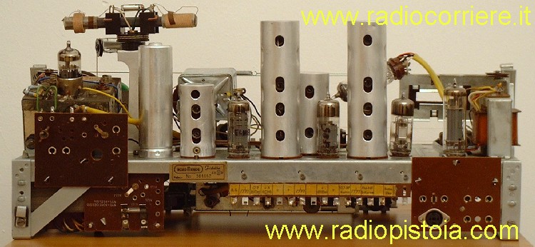
| Detailed rear picture of the chassis until remove from the cabinet. The circuitry is a quite complex but all the wirings (point-to-poin) are exellent. note that in this receiver all the electronic regulations are possibile WITHOUT any necessity to remove the chassis, this because on the bottom of the cabinet there is a hole to use for this purpose. |
|
|
|
|
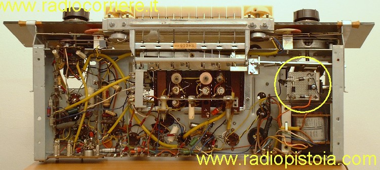
| Internal bottom view of this radio, very... dense :) Inside the yellow circle you can see the rectifier I change becuse its original was broken. Very smart the idea to put all the AF trims and coils accessible from the bottom of the cabinet. |
|
|
|
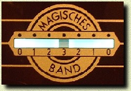
Detailed and elnarged view of the nice mechanism used to switch the tuning indicator on the tuning scale while passing from AM to FM. This permits to keep the tuning scale completly separated, with two indicators. |
|
Enlarged
view of the original broken seleninum rectifier (the red one)
and the new one, made with a classic diodes GRAETZ bridge just
mounted on a little multi-holes board. The original one looks
ok but only without any load. When apply the tubes load the
voltage drop until... 30 volts!
|
 |
 |
In this radio exist an internal ferrite antenna too, wich is possible to move from a knob on the front panel. With this movement is possibile to adjust better the tuning of local and distance stations. Don't forget that this radio was a top class receiver across the '50. |
|
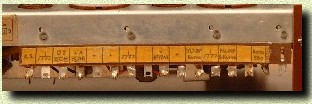
Detailed view of the TEST POINT PLATE, placed on the rear of the chassis, a smart idea very useful. From these TP infact is possibile to check pratically all the receiver, from its anodic voltage to the AGC, the MF discriminator and so on. |
 |
 |
Very close and enlarged view of the magic eye, an EM84 type. With this tuning indicator is possibile to make a fine tuning of the stations, both on AM that in FM. |
|
The
receiver when the restoration has finished, now it looks new
and sounds better! Note the buttons over the tuning scale used
as audio equalyzer. The sound of this radio is really great,
warm, with a great equalization, due to the two elliptic loudspeakers
and the 3D tweeter.
|
|


|
|