|
|


|
| Builder | Unknow |
| Model | Undeterminable |
| Year | 1945 about |
| Bands | AM - SW - Phono |
| Tubes | 5Y3 - 6V6GT - EBC3 - EF9 - EL3 |
| Tuning | Superetherodyne with MF at 455Khz |
| Power | 110-240 Vca |
| Size | 66x30x45 |
| Power audio tube | 6V6GT |
| Magic eye | Not present |
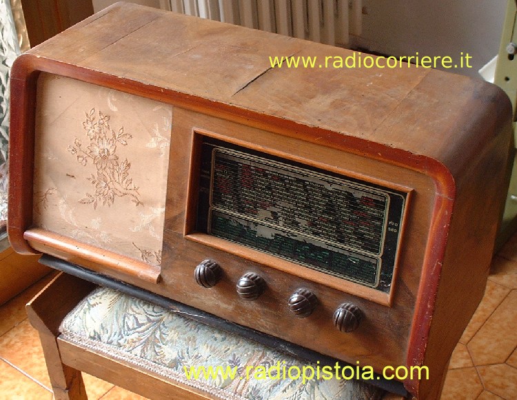 |
Image of this receiver at the begin of its restoration, note the damaged wood cabinet, really in poor conditions. |
|
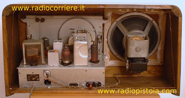
Back view of the receiver, in evident bad state of internal conservation too, with a large quantity of ... historical powder. |
|
|
|
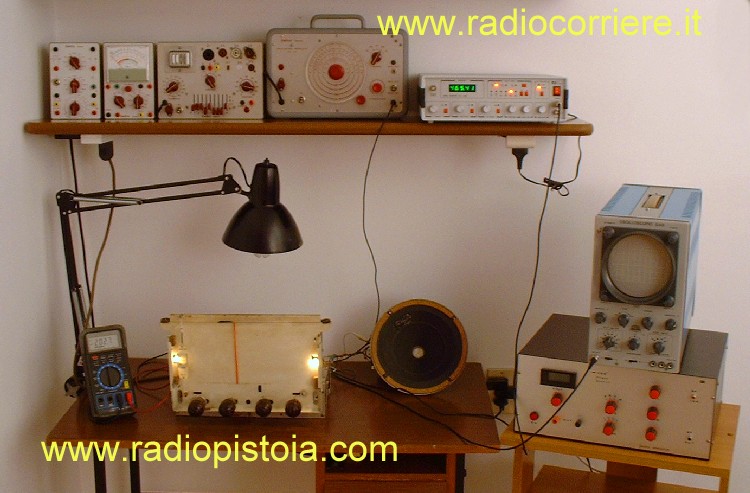
In this image you can see the chassis of the receiver during its power on tests, including the Medium Frequency adjustments. During this tets some calibrated AF signal are sent to the receiver in order to align all the IF transformers. |
|
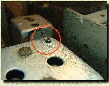
Detailed view of the second MF transformer, in the red circle you can see a little, damaged wire. Often problems like this can cause loss of time during the restoration process. It's very important to make always a great and accurate visual check BEFORE the first power on. |
|
|
|
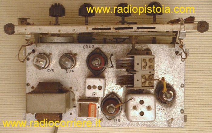
Top view of the receiver. It is a classic superetherodyne radio, with five tubes.
|
|
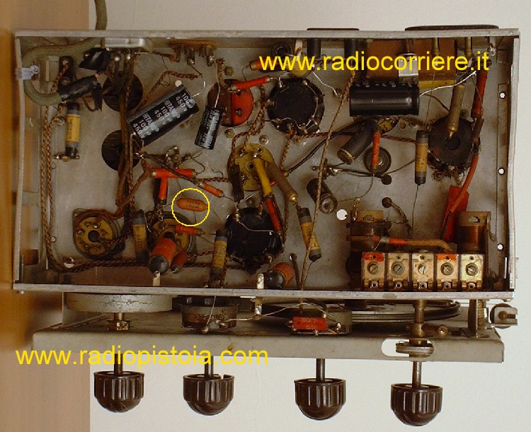
Bottom (internal) view. It's a quite easy schematic, classic, the black capacitors are both wich I changed, the power rectifier ones. In the yellow circle another cap I changed, is "the capacitor" between the last audio preamplifier and the final tube (6V6). Often this cap MUST be replaced, to avoid some grave damages, like the output transformer too. (like in this receiver!!) |
|
|
|
Back view, from the left the power transformer, the IF transformers, the IF amplifier.. |
|
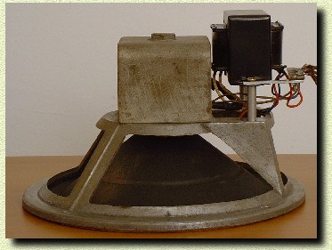
View of the loudspeaker and its output transformer, NEW. The original one was damaged. Probably this radio has been kept powered on for a long time, with a great anodic current, caused by a wrong grid polarization of the final tube (6V6). This wrong grid polarization was caused by the bad capacitor connected from the output of the preamplifier and the grid of the final one. |
|
|
|
Another trouble on this receiver, a bad contact on the BAND SELECTOR, another critial point in these kind of radios. |
|
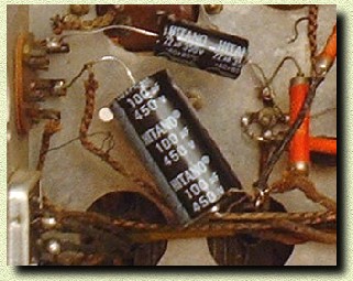
Another internal view, this time of the new power supply capacitors, mandatory to change on so ancient receivers. In other words on each old tube radio these caps could be replaced. A short cirtuit internal on these components may damage the rectifier tube too (in this case a 5Y3) |
|
|
|
Final view of the receiver at the end of its restoration. All work fine, the wood cabinet looks new too. Isn't it? |


|
|