|
|
 |
| Builder | Magnadyne |
| Model | FM-4 |
| Year | 1950 |
| Bands | OM-OC1-OC2....OC9-PHONO |
| Tubes | 6BE6 6J6 EF42 EF42 EQ80 6SQ7 6V6 6E5GT 5Y3GR |
| Tuning | Supereterodyne with M.F. 465Khz and 10.7Mhz |
| Notes | Power audio tube 6V6GT |
| Power | 110-220 Vac |
| Size | 72x29x35 |
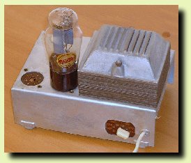 |
Detailed view of the power supply chassis. In this receiver the power is built on another chassis, this to improve the Signal/Noise ratio. |
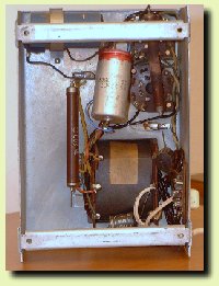 |
Power supply bottom view. You can see the big filter capacitor and the tube socket. |
 |
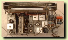
Bottom view of the receiver chassis, from the component side. |
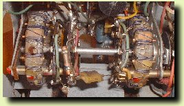 |
Amplitude modulation tuning assembly. Inside a receiver as this with 9 (nine !) bands on short waves you can find a very complex tuning system, like this one. |
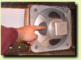 |
View of the large internal speaker. I placed my hand in order to understood the real size od this component. |
1996-2018 ©
Copyright www.radiopistoia.com
- www.radiocorriere.it

